
Since joining the Nanoscale Transport Research Group in September of 2018, I have been involved primarily in the methanol flash cooling setup, overseen by Matthew Ma and Ujash Shah under the leadership of Professor Timothy Fisher, chair of the Mechanical and Aerospace Engineering Department at UCLA. This post details the involvement of fellow undergraduate researcher Austin Tang and myself.
Purpose
The methanol flash cooling setup utilizes the depressurization of methanol to force vaporization and cool a small wafer for applications in transient electronics cooling.
Setup
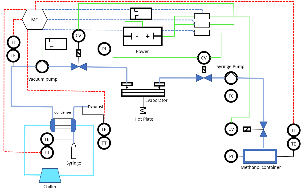
Simply put, the setup involves pumping liquid methanol into a tube next to a heated element which is then exposed to vacuum; this causes vaporization and rapid cooling. This gas is then pumped through a condenser, where the methanol is collected as a liquid to be returned to the methanol storage. This setup is shown below.

P&ID Diagram
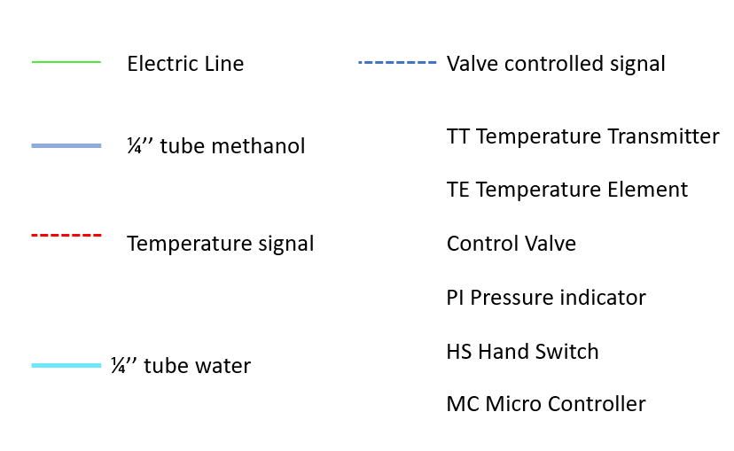
Key
Controls
This setup is dictated by 3 valves: Valve 1 controls flow from the methanol storage, Valve 2 controls flow to the heated element, and Valve 3 Controls flow from the heated element to the vacuum sealed portion of the tubing. During a flash cycle, Valve 3 is left open, exposing the heated element to vacuum pressure and causing immediate flash vaporization when Valve 2 is opened. This is illustrated in the flow chart below.


However, many of these events must occur within fractions of a second of each other, and ideally this system would activate in response to a large spike in heat generation as mitigation. Thus, its operation must be heavily automated. This is where the majority of my contribution has been so far. By integrating valve control and data collection with LabView, all data collection and flash control can be consolidated in one clean front face panel.

This front panel is depicted above, and allows for activation of flash cycles, actuation of data collection, and manual opening/closing of valves for cleaning with helium. The code enabling this is briefly explained below
Cleaning and Flash Cycle

To avoid any operating damage to the vacuum pump, the flash cycle and manual cleaning controls are in opposite cases of the same classical state machine. This means that it is impossible to manually change the state of any valves while a flash cycle is running. Additionally, to avoid damaging the pump, all switch operations are contained within case structures that ensure valves 1 and 2 cannot be opened at the same time; attempts to open 2 while 1 is open will close 1, and vice versa. This protects the vacuum pump from sucking in large quantities of liquid methanol, which would cause significant damage.
These are all contained in an infinite loop; thus, while the flash cycle is off, the code will constantly check the status of the controlling switch.
Data Control

Comments
Post a Comment